













If you are building a projector-based home theater with Dolby Atmos, the ceiling should be coordinated before drywall closes—not after the projector mount, speaker cutouts, recessed lights, HVAC grilles, and wiring have each been finalized separately.
A useful home theater ceiling plan puts those decisions on one drawing. Start with the finished screen and seating positions, map the structure and mechanical constraints, establish valid zones for the overhead speakers and projector, and then add lighting, HVAC, power, wiring, conduit, and service access.
The planning sequence is:
Screen and seating → fixed constraints → Atmos and projector zones → lighting and HVAC → conflict resolution → final locations → prewire
That order matters because moving a symbol on a drawing is easy. Moving a duct, rebuilding a soffit, reopening drywall, or discovering that a projector mount occupies an Atmos speaker location is not.
What Does a Home Theater Ceiling Plan Actually Solve?
A ceiling plan, reflected ceiling plan, prewire plan, and wiring diagram may appear similar, but they answer different questions.
| Planning document | What it helps you decide | What it does not solve by itself |
|---|---|---|
| Home theater ceiling plan | Where the projector, overhead speakers, lights, HVAC, structure, and ceiling features can coexist | Detailed equipment connections or final system calibration |
| Reflected ceiling plan (RCP) | How overhead and visible ceiling elements are organized on a coordinated architectural drawing | The AV performance decisions behind each location |
| Home theater prewire plan | Where speaker wire, signal cable, power, control cable, and conduit should terminate before surfaces close | Whether those endpoints were positioned correctly |
| Home theater wiring diagram | How components connect and where signals travel | Physical conflicts among speakers, lights, joists, ducts, soffits, and projector hardware |
A reflected ceiling plan is an established architectural drawing type for communicating ceiling information. Autodesk treats an RCP as a dedicated plan view used to show ceiling elements and coordinate them with the space below. You can follow the same logic without pretending that a simple homeowner drawing is a complete professional construction document.
The practical goal is one coordinated overhead view that answers:
If the ceiling is built exactly as shown, will all of these systems still work together?
The prewire plan should come out of that decision. It should not replace it.
What Should Your Home Theater Ceiling Layout Show?
At minimum, the working plan should reference:
- the finished screen or projected image area;
- the primary listening position and other important seats;
- seating rows and risers;
- the projector lens-position or mounting zone;
- overhead speaker locations or valid placement zones;
- joists, beams, blocking, and other structural constraints;
- soffits and ceiling-height changes;
- HVAC supplies, returns, and major duct restrictions;
- recessed lights, decorative fixtures, and ceiling fans;
- acoustic panels, star ceilings, or other ceiling treatments;
- access panels and equipment that must remain serviceable;
- projector power and signal destinations;
- speaker-wire destinations;
- conduit and future cable paths.
You do not need advanced CAD software to discover many of the conflicts. An accurate, dimensioned drawing with separate layers can already reveal a great deal—as long as it represents the finished theater in use, not an empty room.
Step 1: Start With the Screen and Seating
A common planning mistake is to begin with a visually balanced ceiling grid. The lights are centered, the speaker cutouts are symmetrical, and the projector sits on the room centerline. Only later does someone confirm where people will sit.
For a theater, that sequence is backwards.
Dolby’s overhead-speaker layouts establish speaker relationships from the listener’s position. CEDIA/CTA RP22 also treats the listening area, screen geometry, seating risers, speaker placement, and real-room constraints as connected design variables.
Before locking any ceiling locations, mark:
- The primary listening position: the main reference point for important audio decisions.
- The complete listening area: especially important when several seats or two rows matter.
- The finished row positions: not temporary sofa symbols that may later move.
- Riser height: a raised rear row changes listener height and may affect projector clearance.
- The occupied seat profile: include likely head positions, headrests, and reclined seating conditions.
The ceiling should be coordinated around the room while people are using it. If you are still deciding row spacing, viewing distance, or available clearance, confirm those fundamentals with the home theater dimensions guide before treating ceiling points as final.
Step 2: Map the Constraints That Are Difficult to Move
Next, add the physical conditions that already limit usable ceiling space:
- joists and beams;
- blocking and structural supports;
- soffits and ceiling-height transitions;
- ductwork and pipes;
- existing electrical boxes;
- access openings;
- shallow ceiling cavities.
This layer answers a question that renderings often hide: Is there actually enough space above the finished ceiling for the item shown on the drawing?
An apparently open speaker location may contain a joist. A perfectly centered projector may lack suitable mounting structure. A recessed light may occupy the only cavity deep enough for an overhead speaker.
Finding those conditions on paper preserves options. Finding them after a cutout has been made creates compromises.
Step 3: Establish Atmos Speaker Zones
Bring the intended overhead-speaker layout into the plan only after the seating references and physical constraints are visible.
Do not begin by making four speaker symbols look symmetrical against the lighting grid. Start from the listening position and the guidance for the Atmos configuration you intend to build. The Dolby 5.1.4 overhead speaker guide, for example, defines speaker relationships around the listener rather than around decorative ceiling features.
At this stage, it is often more useful to mark acceptable speaker regions rather than exact cutout centers. The final position can still depend on:
- the intended channel configuration;
- the primary and secondary seats;
- ceiling height;
- speaker type and aiming capability;
- cutout size and mounting depth;
- joists, ducts, soffits, and other ceiling devices.
If one proposed Atmos position lands on a joist or duct, do not slide only that speaker until it physically fits. Recheck the overhead layout as a system. For the wider choice between height-channel configurations and speaker types, use the Dolby Atmos home theater setup guide; keep this ceiling plan focused on where the chosen system can coexist with the room.
Step 4: Bring In a Verified Projector Zone
The projector should enter the plan as a verified mounting range, not as an icon placed wherever the ceiling appears open.
The selected model affects its optical range, chassis dimensions, mount position, ventilation, cable access, and service requirements. Epson’s model-specific installation guidance, for example, addresses compatible mounting, positioning, and unobstructed ventilation rather than offering one universal clearance rule for every projector.
Carry the following information into the ceiling plan:
- the usable projector-position range;
- the lens location;
- the chassis and mount footprints;
- the required mounting structure;
- intake and exhaust areas;
- connector access;
- future service access.
The detailed throw-distance and image-alignment work belongs in the projector setup process. Once the model and screen establish where the projector can work, the ceiling plan tests how that valid zone interacts with everything else overhead.
Step 5: Add Lighting, HVAC, and Ceiling Features
Once the Atmos and projector zones are visible, overlay the lighting layout and other ceiling features.
Ask:
- Does a recessed light occupy an important Atmos speaker zone?
- Does a fixture reduce the available projector-mounting range?
- Could a pendant or ceiling fan enter the projected light path?
- Will bright trim or a fixture create distracting light near the screen?
- Does a decorative ceiling grid block speaker installation?
- Will an acoustic or star-ceiling feature cover equipment access?
A perfectly symmetrical ceiling can still be poorly coordinated if its visual pattern forces every AV component into a second-choice location. The reverse is also true: equipment should not be scattered carelessly merely because each item works on its own.
This coordination step determines where fixtures can coexist. Decisions about dimming, screen-zone glare, safety lighting, and lighting scenes belong in a dedicated home theater lighting setup guide.
HVAC belongs on the same drawing because it occupies the same physical space. Show the relevant supply and return grilles, soffits, major ducts, and mechanical access points.
Do not assume an HVAC grille can simply be moved to accommodate a speaker. Airflow, duct routing, noise, room loads, structure, and mechanical requirements may constrain its location. The ceiling plan makes the interface visible; the responsible HVAC professional determines what can safely change.

Step 6: Resolve Conflicts by Comparing Constraints
When two items overlap, do not immediately move whichever one appears easier. First identify why each item needs to be there and how much flexibility each side actually has.

| Conflict | Easy but risky reaction | Better question to ask |
|---|---|---|
| Atmos speaker overlaps a recessed light | Move the speaker a few inches | How much flexibility exists in the speaker geometry compared with the lighting pattern? |
| Projector zone overlaps an overhead speaker | Install whichever system is easier | What valid positions remain for both systems? |
| A duct blocks the preferred speaker location | Assume calibration will compensate | Can the speaker layout, speaker type, or mechanical route change without undermining the intended result? |
| Projector sits near an HVAC element | Assume visible clearance is enough | What does the exact projector require for ventilation, mounting, cable access, and service? |
| A soffit cuts through the projector zone | Rely heavily on digital correction | Does another valid optical position exist for the selected projector and screen? |
| A decorative ceiling covers a speaker region | Move the speaker to the nearest panel edge | Can the decorative layout be coordinated around the validated AV zones? |
| An access panel becomes hidden | Plan to open the ceiling later | How will the concealed equipment or building system actually be serviced? |
| The rear row approaches the projector beam | Check only the empty seats | What happens with actual occupants, raised headrests, and reclined seating? |
This method prevents a common coordination mistake: solving the visible collision without understanding why both items were placed there.
Sometimes the light should move. Sometimes the projector still has another valid position. Sometimes the overhead-speaker layout needs to be reconsidered as a group. Sometimes the structure or mechanical system imposes the real limit.
The drawing should expose that decision, not pretend every conflict has the same answer.
CONFIRM THE FLOOR BEFORE THE CEILING
Is Your Seating Layout Ready for Ceiling Coordination?
Confirm row positions, recline space, aisles, and viewing relationships before permanent speaker, projector, and wiring locations are marked overhead.
How Two Seating Rows Change the Ceiling Plan
Consider a theater with two seating rows, a raised rear row, four overhead speakers, a ceiling-mounted projector, recessed lighting, and a rear soffit containing part of the HVAC system.
If each system is planned separately, the rear portion of the ceiling can become crowded quickly. The soffit may reduce the projector range, a rear overhead-speaker zone may compete with ductwork, and the original lighting grid may occupy the remaining usable cavities.
The stronger workflow begins on the floor:
- Mark the screen, both rows, primary listening area, and riser.
- Add the soffit, ductwork, ceiling heights, and structure.
- Overlay valid Atmos speaker regions.
- Overlay the verified projector zone.
- Add lighting and other ceiling features.
- Resolve the overlaps while several valid options still exist.
The second row changes more than the seat count. It can introduce higher head positions, another important listening area, different projector-beam clearance, additional lighting needs, and a rear soffit or ceiling-height transition. If a raised row is part of the plan, confirm its effect on sightlines, platform depth, and head clearance with the home theater riser planning guide.
If the projector clears the chair but not the person sitting in it, the plan has not passed. Furniture dimensions are not merely purchasing data in a projector-based theater; they can become part of the AV geometry.
Step 7: Turn the Coordinated Plan Into a Prewire Plan
Prewiring is valuable because hidden cable routes become harder to change after drywall. But early wiring only helps when its endpoints are based on stable decisions.
A speaker-wire stub should not determine an Atmos location that was never checked against the seating. A ceiling outlet should not determine the projector position when the model and mounting range remain unknown. A conduit should not terminate behind the wrong side of a soffit simply because it was installed first.
The correct sequence is:
Room references → valid equipment zones → conflict resolution → final destinations → prewire
Once the destinations are confirmed, document:
- speaker-wire endpoints and labels;
- projector power and signal destinations;
- cable routes back to the equipment location;
- conduit paths and pull access;
- blocking and mounting support;
- junctions and access panels;
- spare pathways planned for future changes.
For a closer look at cable routes, wall cavities, and concealed connections, continue with the guide to in-wall home theater wiring. Wiring methods, power work, in-wall cable ratings, conduit requirements, and applicable codes should still be confirmed for the actual project rather than copied from a generic diagram.
Confirm Product-Specific Data Before Final Cutouts
General planning can establish useful zones. Permanent openings require exact product information.
| Item | Data to confirm before installation |
|---|---|
| Projector | Exact model, lens position, mounting range, chassis dimensions, mount footprint, ventilation, connector access, and maintenance access |
| Overhead speakers | Model, cutout dimensions, mounting depth, required clearance, aiming capability, and installation instructions |
| Lighting | Fixture diameter, housing depth, driver or junction-box requirements, dimming plan, and service access |
| Seating | Final row position, upright and reclined depth, headrest height, occupied head position, and riser height |
The purpose is not to collect specifications for their own sake. It is to replace assumptions with installable geometry.
Take Photos Before Drywall Hides the Work
Once the coordination is complete and the infrastructure is installed, photograph every ceiling section before insulation, drywall, acoustic treatment, or decorative panels conceal it.
A useful record includes:
- wide photos showing location context;
- close-ups of cable destinations and labels;
- conduit paths;
- blocking and projector support;
- junction locations;
- duct routes that affect future work;
- unusual framing;
- spare pathways and access points.
Save the photos with the final marked-up plan and its revision number. “Cable somewhere above the rear row” is not useful documentation three years later. A labeled destination tied to a drawing and a context photo is.
Home Theater Pre-Drywall Checklist
Before the ceiling closes, review the plan as a handoff document rather than asking only whether the drawing looks finished.
| Planning item | Confirmed | Still open | Who needs to confirm? |
|---|---|---|---|
| Finished room dimensions and ceiling heights | |||
| Final screen and projected image position | |||
| Final seating rows and primary listening area | |||
| Riser location and height | |||
| Overhead speaker layout and speaker model | |||
| Projector model or verified mounting zone | |||
| Projector support, ventilation, and service access | |||
| Joists, beams, blocking, soffits, and ducts | |||
| HVAC supply and return locations | |||
| Lighting, ceiling fan, and decorative features | |||
| Access panels and service routes | |||
| Power, speaker wire, signal cable, and conduit | |||
| Remaining ceiling conflicts | |||
| Current drawing revision identified | |||
| Pre-close photographs completed |
This checklist does not replace manufacturer instructions or structural, electrical, HVAC, fire-protection, and code requirements. Its job is to stop those requirements from being coordinated on disconnected drawings.
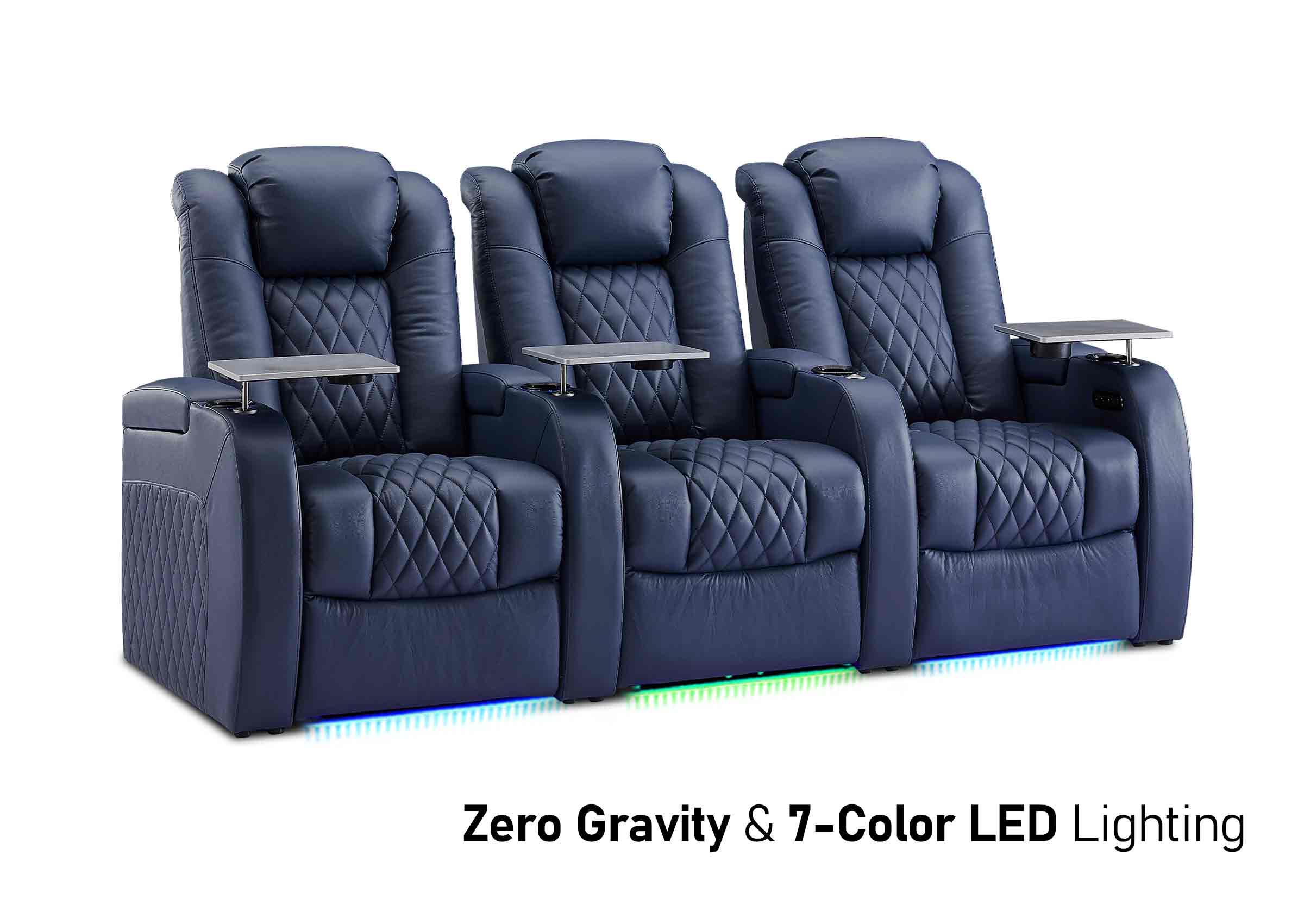
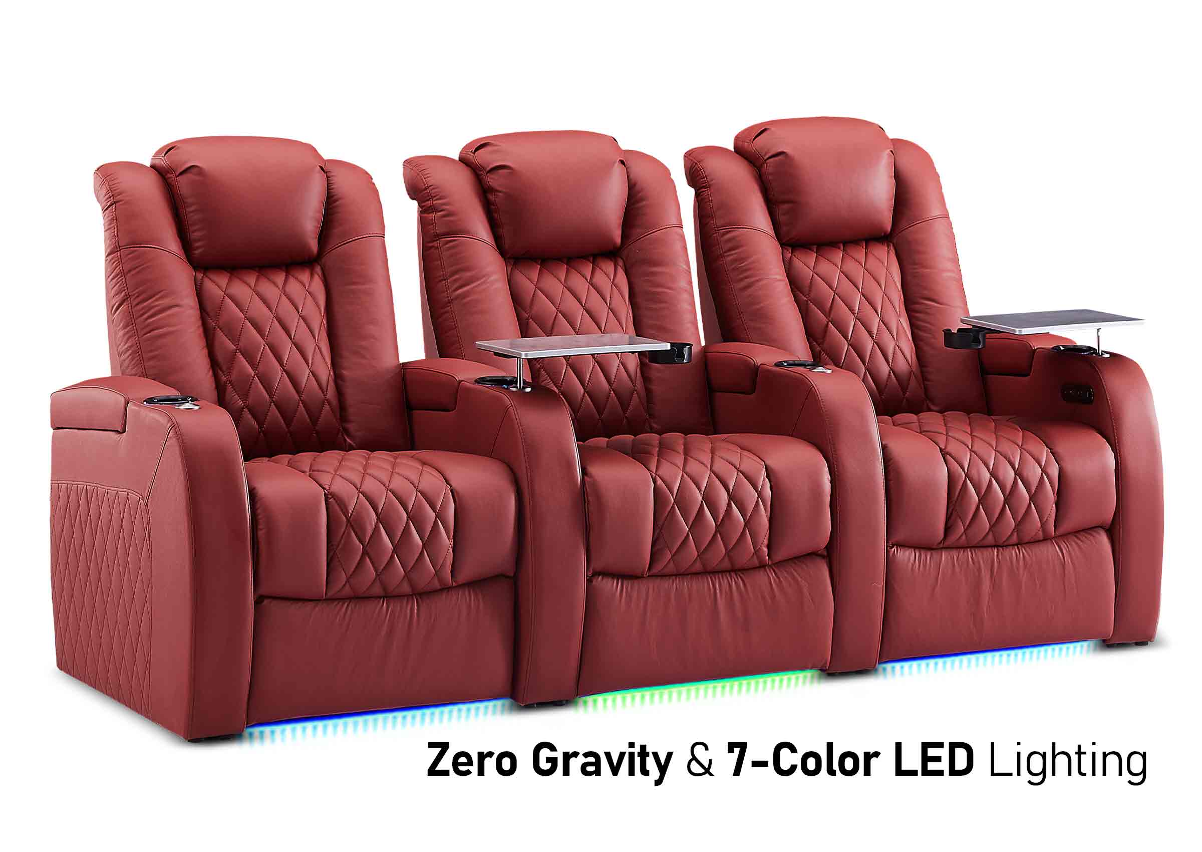
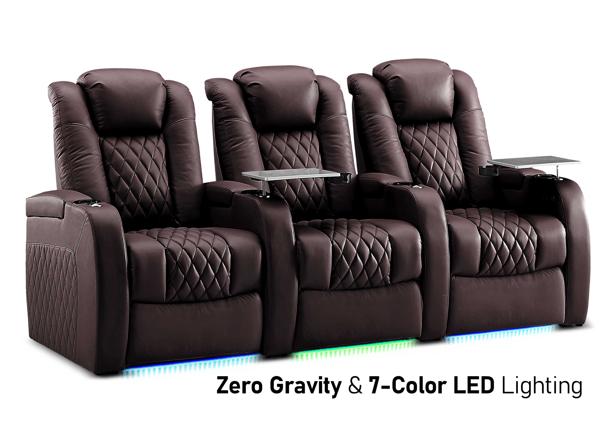
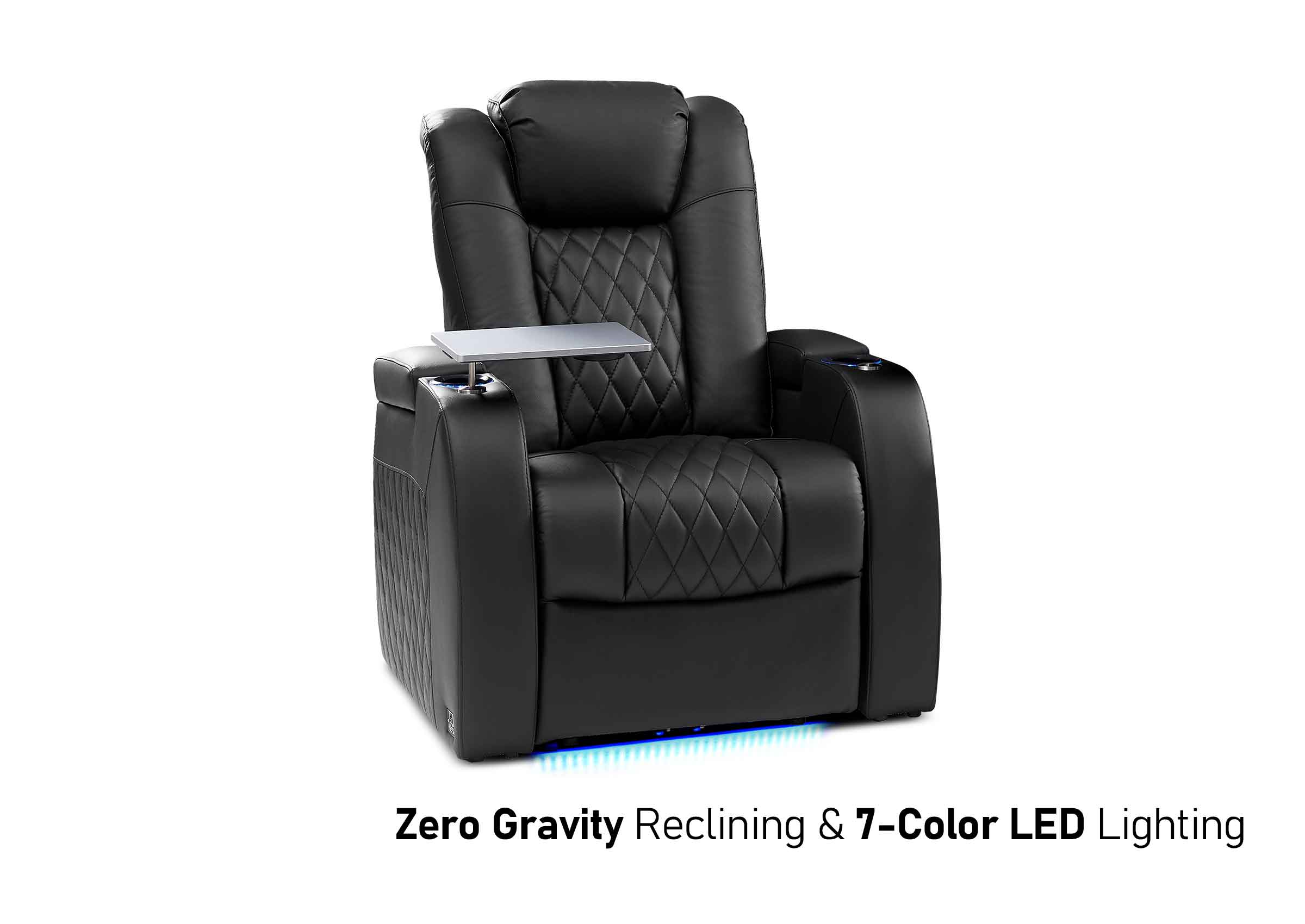
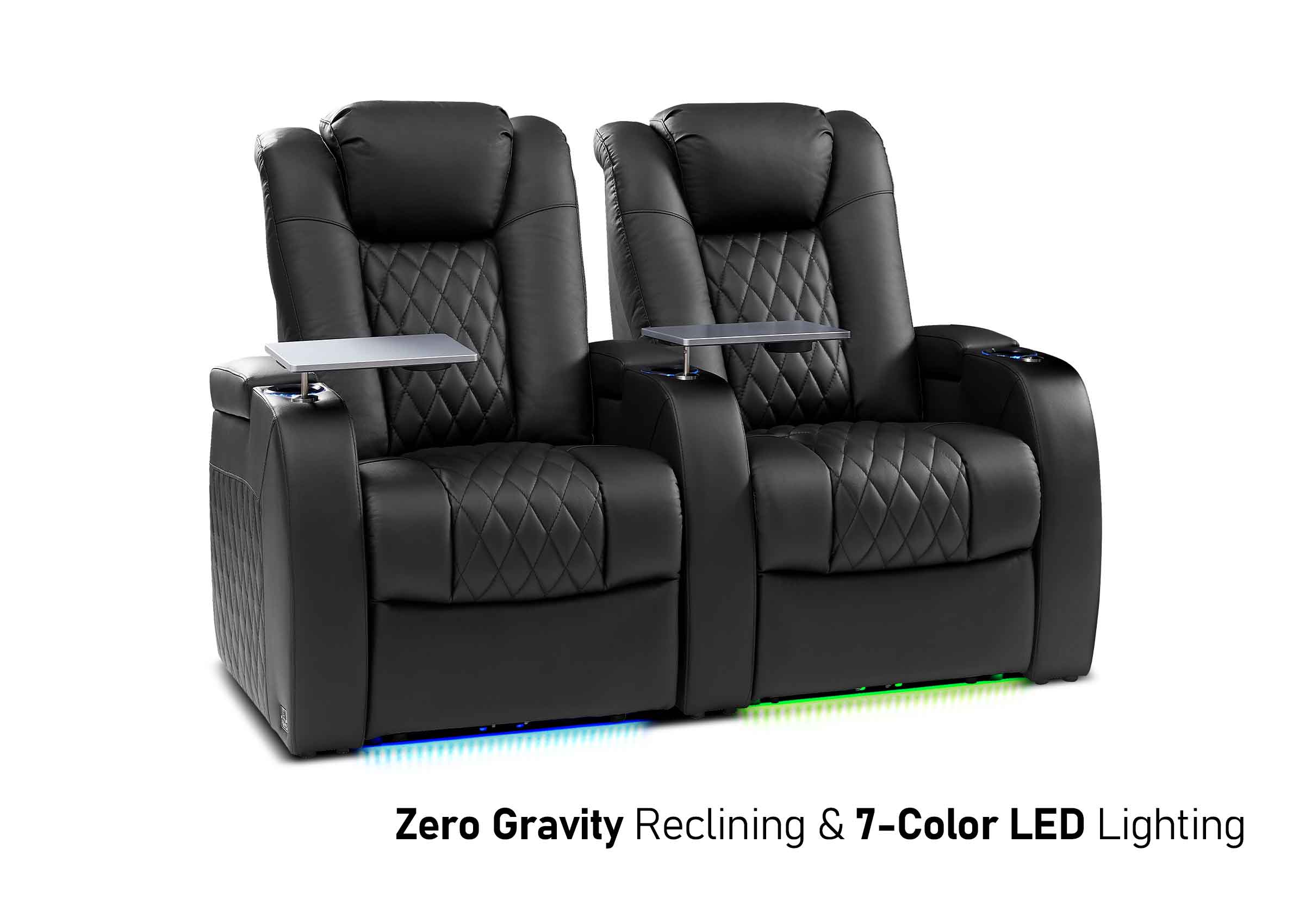
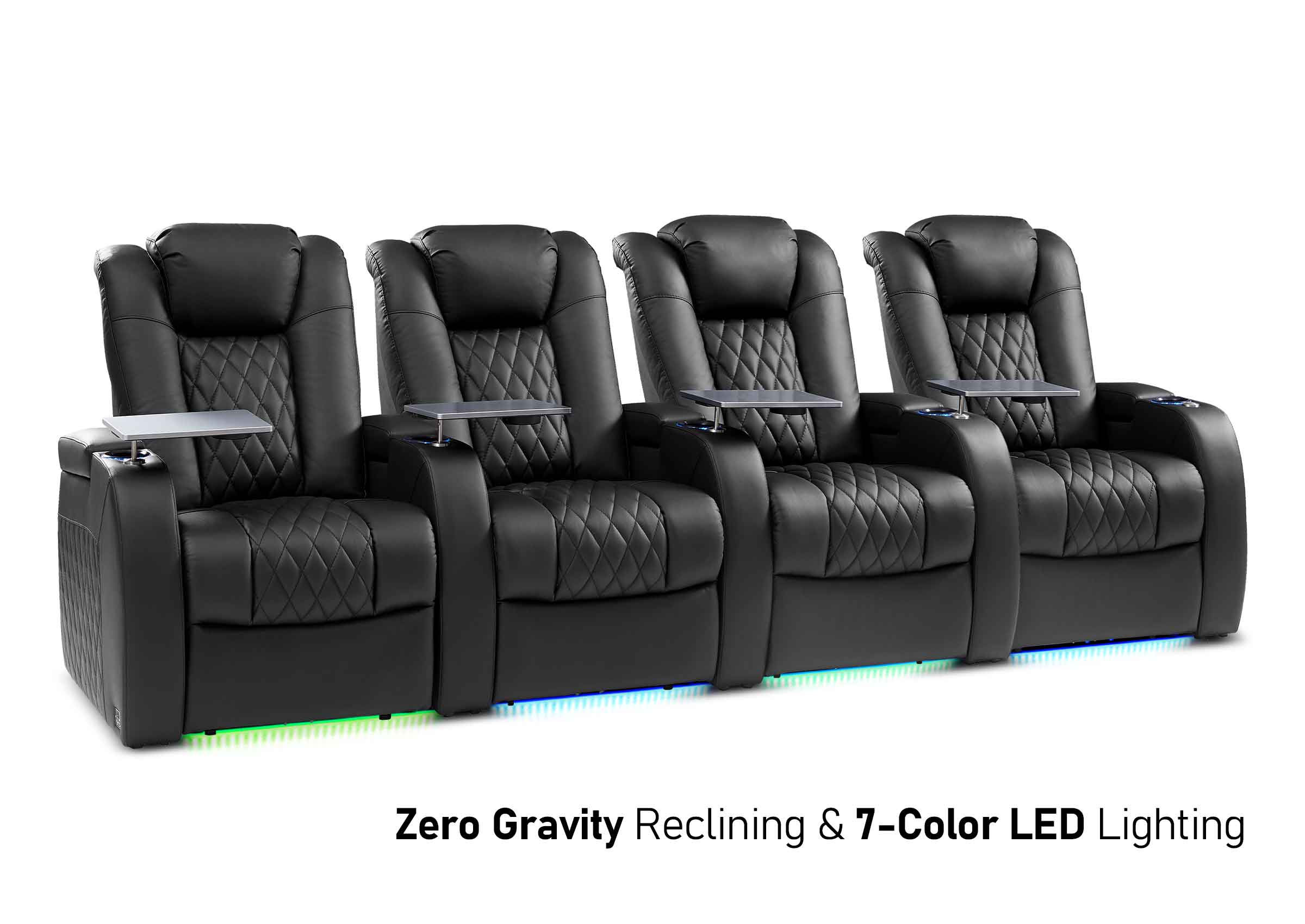
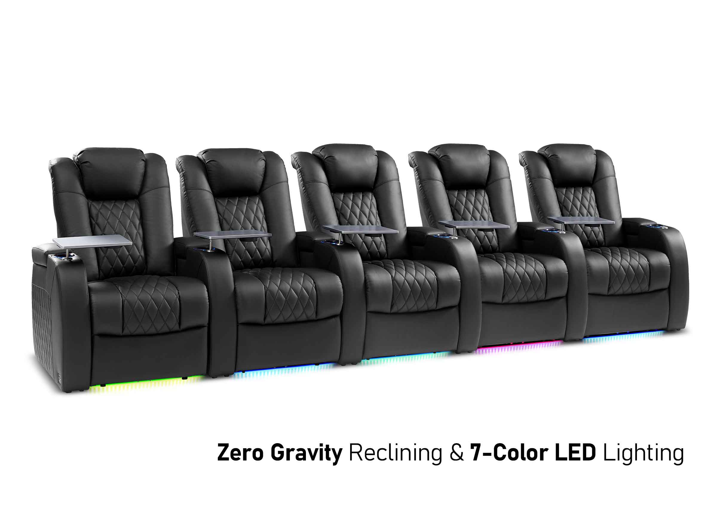
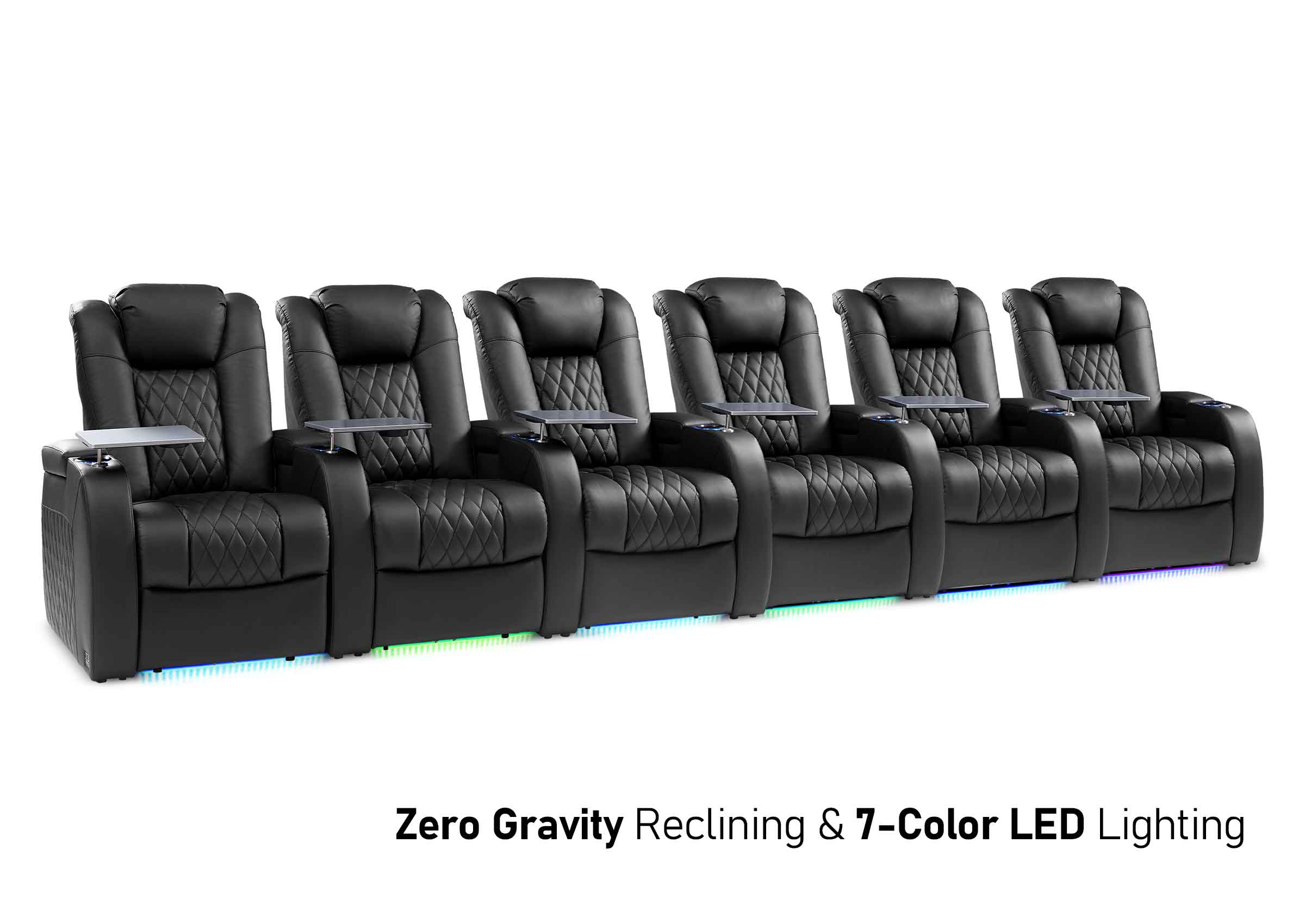
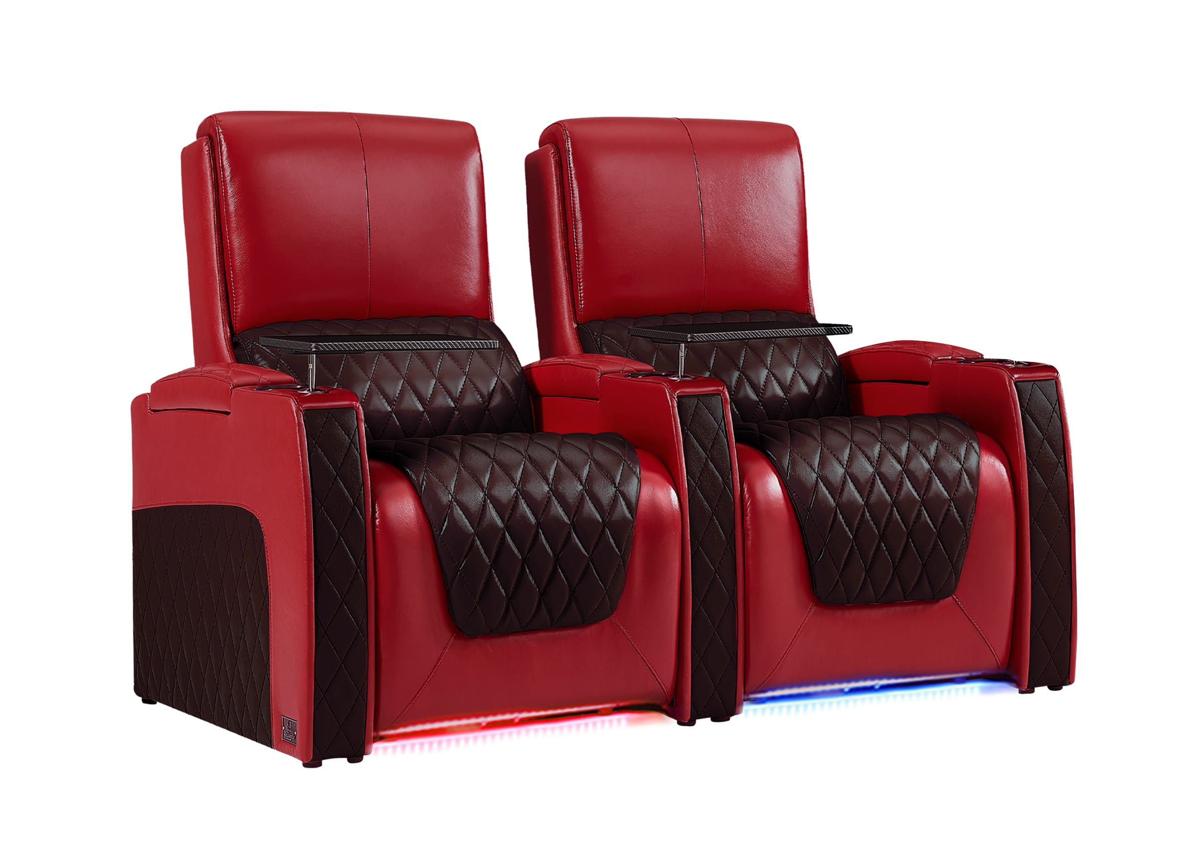
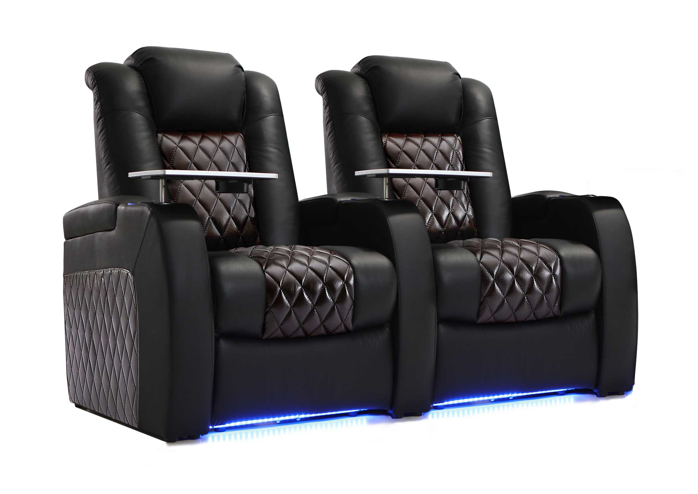
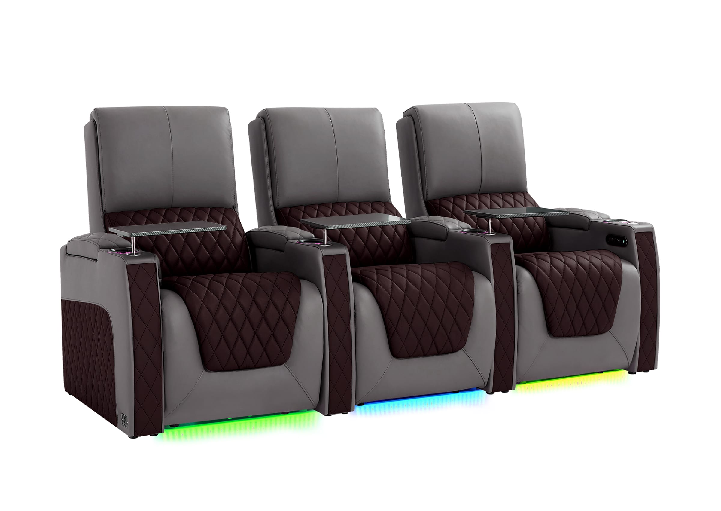
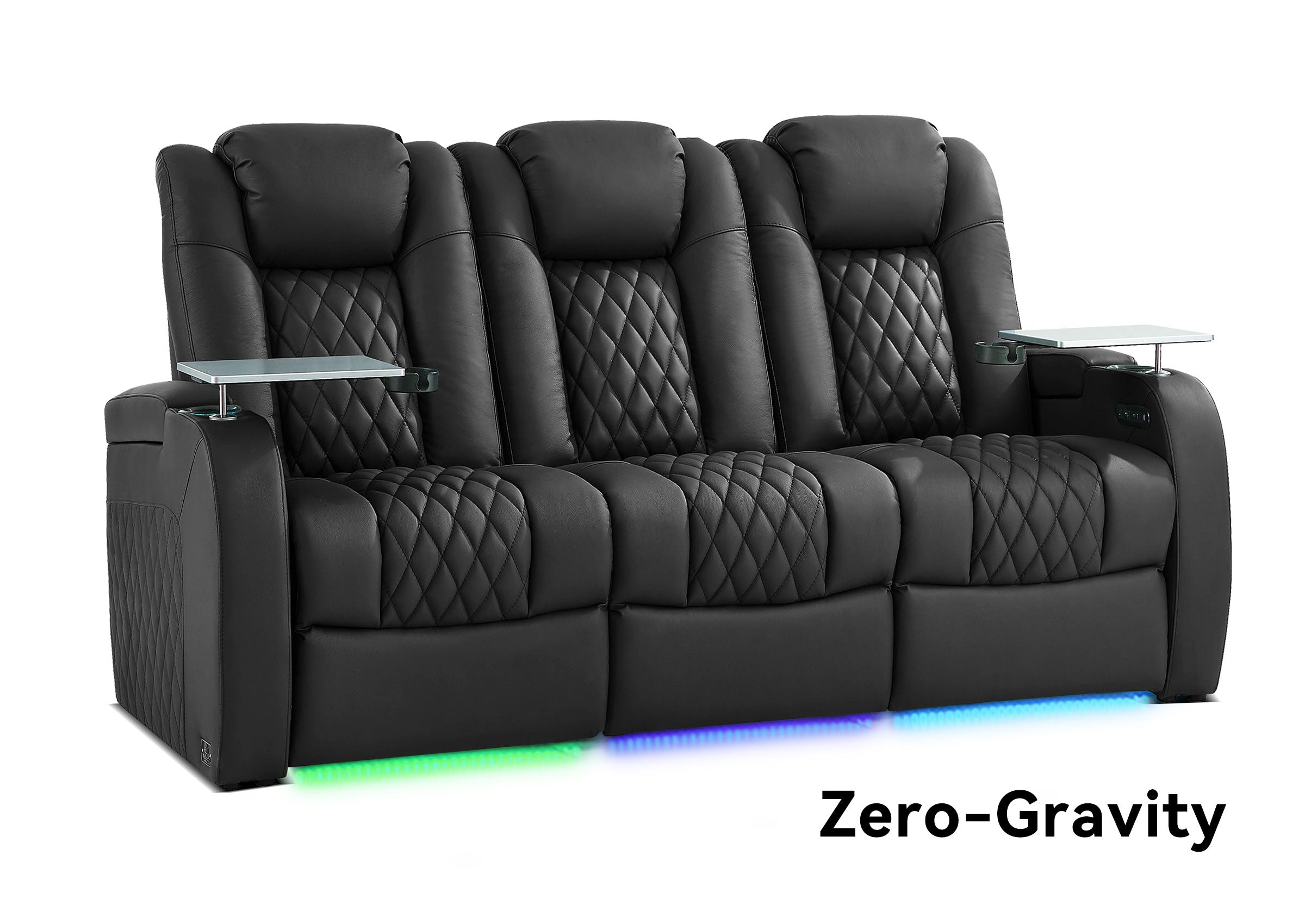
If this ceiling plan is part of a designer-led, multi-row, or custom private theater, the seating configuration may also need to be coordinated with room dimensions, row positions, finishes, and other project requirements. You can discuss a custom theater seating project with Weilianda once those seating-related inputs are ready. AV, structural, electrical, and HVAC decisions should remain with the appropriately qualified project professionals.
Frequently Asked Questions
Is a home theater ceiling plan the same as a reflected ceiling plan?
They can overlap, but they are not always identical. An RCP is an established architectural drawing convention for ceiling elements. A home theater ceiling plan can use that convention while adding AV-specific references such as the listening area, overhead-speaker zones, projector mounting range, and prewire destinations.
Should the projector or Atmos speakers be positioned first?
Begin with the final room, screen, seating position, and listening area. Then establish the valid geometry for the overhead-speaker layout and the model-specific projector zone. Overlay both before either becomes a permanent ceiling opening.
Can an Atmos speaker be moved to avoid a recessed light?
Possibly, but the change should be checked against the listening position and the intended speaker layout. If the lighting pattern has more flexibility than the audio geometry, moving the light may preserve a better result.
Should seating be finalized before home theater prewire?
The seats do not need to be physically installed, but their row locations and relevant dimensions should be reliable. Moving a row can change the audio reference, viewer height, projector-beam clearance, and final wire destinations.
Do HVAC vents belong on the home theater ceiling plan?
Yes. They share the ceiling with speakers, lights, projector hardware, acoustic features, and access points. Their engineering remains the responsibility of the appropriate professional, but their locations belong on the coordination drawing.
Do You Need a Professional RCP for a Small Home Theater?
Not always. A straightforward single-row room may be coordinated with an accurate dimensioned plan and careful field verification. Professional design becomes more valuable as the number of dependencies increases, such as multiple rows, low ceilings, extensive soffits, complex Atmos layouts, projector enclosures, integrated lighting, or substantial mechanical work.
What If the Home Theater Has a Low Ceiling?
A low ceiling reduces the space available for raised seating, deep in-ceiling speakers, projector hardware, soffits, ducts, and decorative treatments. Map the finished height and every intrusion before choosing equipment. The guide to low-ceiling home theater planning covers the broader room and seating tradeoffs.
What If the Ceiling Is Already Finished?
Document what is already fixed, including lights, HVAC, soffits, accessible framing, existing wiring, and service openings. Then identify the remaining valid equipment zones. Avoiding unnecessary demolition may become a stronger constraint, so the equipment choice or mounting approach may need to change.
The Best Ceiling Plan Is a Decision Map
A successful home theater ceiling plan is not the drawing with the most symbols. It is the one that makes the important relationships visible before someone cuts the ceiling.
Begin with the finished room and the people sitting in it. Map the conditions that cannot move easily. Establish valid Atmos and projector zones before choosing exact points. Add lighting, HVAC, structure, service access, and wiring to the same view. Then resolve every overlap by asking why each location matters and what can genuinely change.
Once those decisions are coordinated, prewire becomes the result of the plan—not a collection of guesses hidden behind drywall.
If you still need help confirming how the seating configuration fits the room, visit Weilianda Support or email leon@weiliandahome.com.